


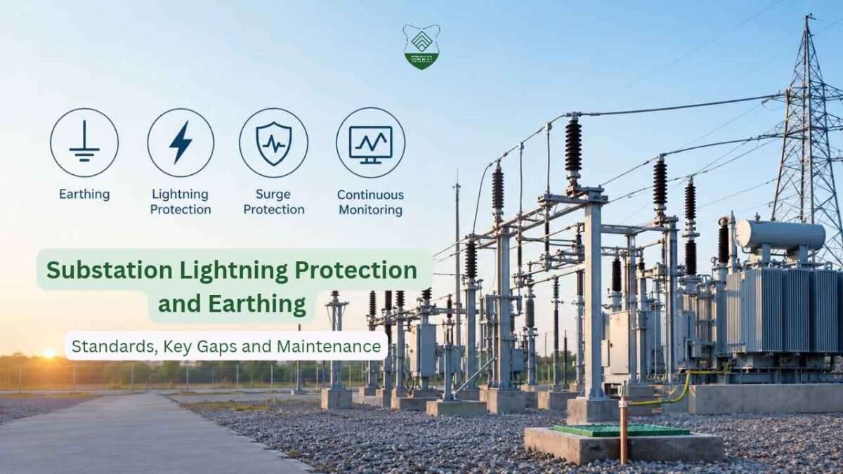

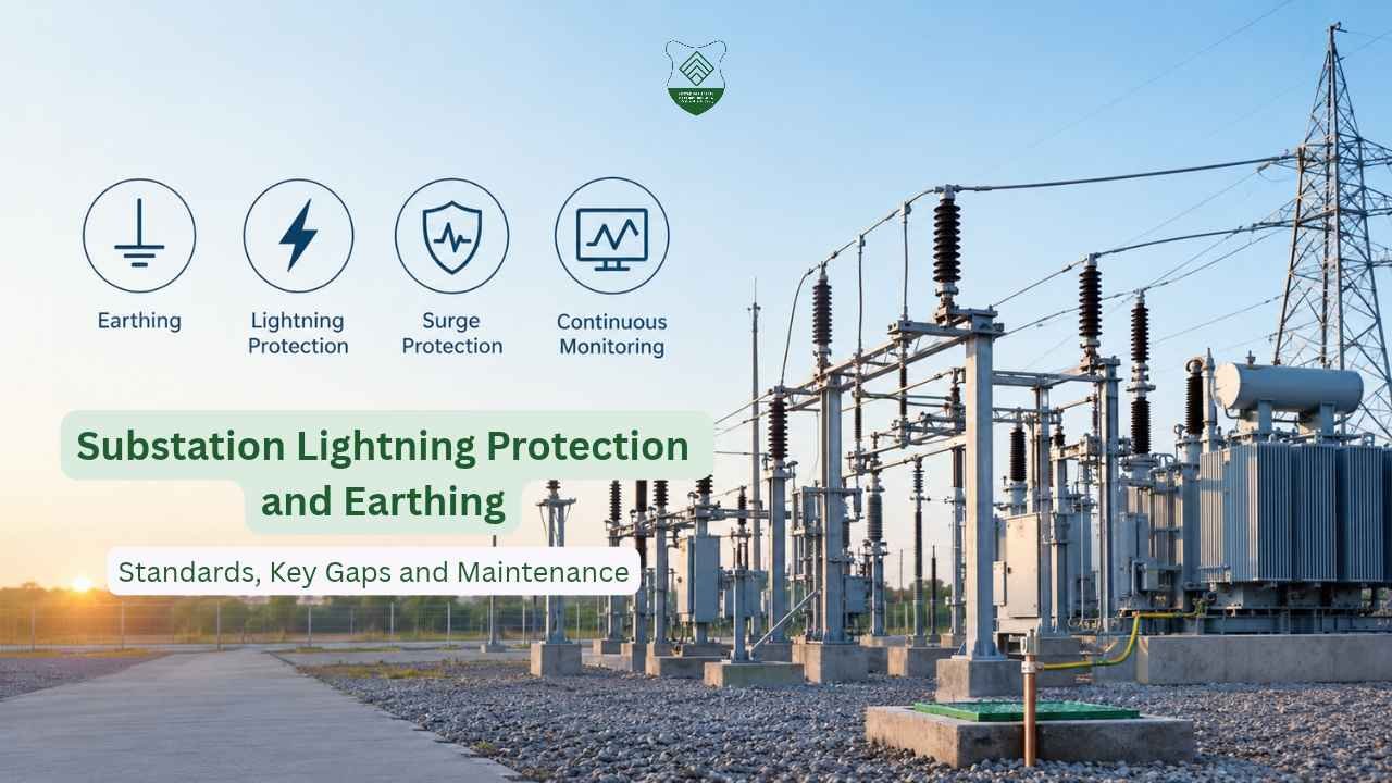
Substation earthing and lightning protection systems are the foundation of electrical safety, equipment protection and grid stability. A degraded grounding grid can lead to Ground Potential Rise (GPR), insulation breakdown, relay maloperation and dangerous step and touch voltages for operating personnel. A well-structured Safety Training Program in Kolkata can help electrical and safety professionals understand how earthing, lightning shielding, surge protection and monitoring work together to protect critical power infrastructure.
Key Standards Governing Substation Protection
Substation protection rests on a mix of Indian statutory requirements and international guidelines:
- CEA (Measures Relating to Safety and Electric Supply) Regulations, 2023: statutory safety, earthing and clearance requirements for Indian utilities.
- IS 3043: the code of practice for earthing, covering soil resistivity measurement (Wenner 4-pin method) and conductor sizing.
- IS/IEC 62305: lightning protection, including risk management, structural protection and surge protection devices.
- IEEE Std 80: calculation of safe step and touch potentials, grid conductor sizing and grid resistance.
- IEEE Std 998: direct lightning stroke shielding using the Rolling Sphere Method and Electro-Geometric Model with shield wires and masts.
- IEEE Std 837: qualifying permanent grounding connections such as exothermic welds.
- IEC 60099-4: gapless metal-oxide surge arresters.
- IEC 61936-1: design, safety clearances and earthing for power installations above 1 kV AC.
Earth Resistance Benchmarks and Testing
Low, stable grid resistance ensures rapid fault clearance and operator safety. The benchmarks in the technical report are:
- EHV/UHV substations (220 kV, 400 kV, 765 kV): grid resistance of about 0.2 Ω to 0.5 Ω or below.
- HV substations (33 kV, 66 kV, 132 kV): 1.0 Ω or below.
- Transformer and reactor neutral earth pits, and control room earth: 1.0 Ω or below.
The grid should be tested at least once every 12 months, ideally twice (pre-monsoon and post-monsoon), using the Fall-of-Potential method. Large grids may need high-frequency or heavy-current injection to overcome stray currents. Infrared thermography of earthing risers, busbar connections and surge arrester earth leads adds another layer of inspection.
Why Earth Grid Degradation Is a Safety Concern
Underground grids degrade invisibly. The main causes are:
- Galvanic and soil corrosion: mild steel and GI flats corrode quickly in acidic, alkaline, moist or salty soils.
- Thermal shock: repeated high fault currents (25 kA to 50 kA) overheat joints and cause micro-fractures.
- Leaching of chemical backfills: bentonite and earth-enhancing compounds wash away, raising electrode contact resistance.
- Mechanical disturbance: excavation, civil works or cable trenching can sever buried conductors.
This is a core topic in an Industrial Safety Course in Kolkata, especially for personnel responsible for substation maintenance. When grid resistance rises above 1.0 Ω, GPR (V = I fault × R grid) can damage control cables, telecom equipment and auxiliary supplies. Touch and step voltages may exceed IEEE Std 80 limits, and surge arresters may fail to discharge surges effectively. That can cause internal flashovers in CTs, PTs and transformer bushings.
Key Maintenance Gaps
- Blind spots in annual testing: a yearly test gives one static value, so a grid disconnection or riser breakage between tests goes unnoticed.
- Unmonitored surge arresters: MOV degradation from repeated strikes stays hidden until thermal runaway.
- Isolated pit versus grid integrity: a single pit may test below 1.0 Ω even though the main underground loop connecting it to the switchyard has broken.
From Periodic Testing to Continuous Monitoring
Modern substations are moving to condition-based management:
- Earth Resistance Monitoring Systems (ERMS): online sensors inject low-frequency signals into grid risers without interrupting service, and raise SCADA/SAS alarms when resistance exceeds a preset threshold (for example, 0.5 Ω).
- Smart surge protection diagnostics: third-harmonic leakage current monitoring (per IEC 60099-5) detects MOV degradation before failure, while SCADA-integrated lightning counters log stroke magnitude, duration and timestamp to trigger post-strike inspections.
- High-integrity grid construction: exothermic welding (IEEE 837) replaces bolted or standard arc-welded joints, and equipment frames, breaker bases and operating handles are double-bonded to two independent risers on opposite sides of the structure.
Fire, Life and Site Safety Measures
Earthing works alongside other safeguards: a 100 mm to 150 mm layer of crushed high-resistivity gravel to raise foot contact resistance, fire barrier walls and oil soak pits for transformers, nitrogen injection or high-velocity water spray fire protection, arc flash assessment per IEEE 1584, strict LOTO procedures, and SF6 leak detection and oxygen depletion monitoring in GIS halls.
Effective substation safety depends on sound design, regular testing, quality connections and continuous monitoring. The biggest sources of error are ageing, environmental degradation and human oversight, and a continuous cycle of study, rectification and monitoring is the best way to reduce them. A practical Safety Training Program in Kolkata or Industrial Safety Course in Kolkata can give professionals the knowledge to identify grounding risks and keep critical electrical systems safe.
Recent Post
Hierarchy of Controls: Applying the Five Levels to Electrical, Earthing…
Substation Lightning Protection and Earthing: Standards, Key Gaps and Maintenance…
HIRA vs Risk Assessment: What Every Safety Professional Should Know…